Why
I have an R.A. Microjets miniature turbojet with a dead factory ECU. Replacement controllers exist, but where’s the fun in that. An engine controller is a perfect excuse to build a complete embedded product: board, firmware, protocol, tooling, and the safety story that makes you willing to stand next to the thing.
The board
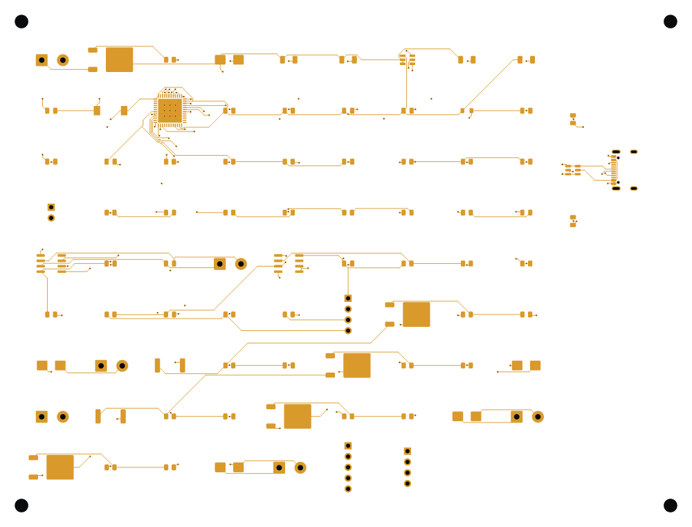
A 4-layer STM32G431 board designed entirely from Python scripts driving headless KiCad: netlist, placement, autorouting, and verification, with no hand-drawn schematic. Final board: 163×124 mm, 87 components, 55 nets, 0 DRC violations, 0 ERC errors, 0 schematic-parity issues. Fabricated at JLCPCB with a fully verified DigiKey BOM and a per-pin GPIO audit against the datasheet.
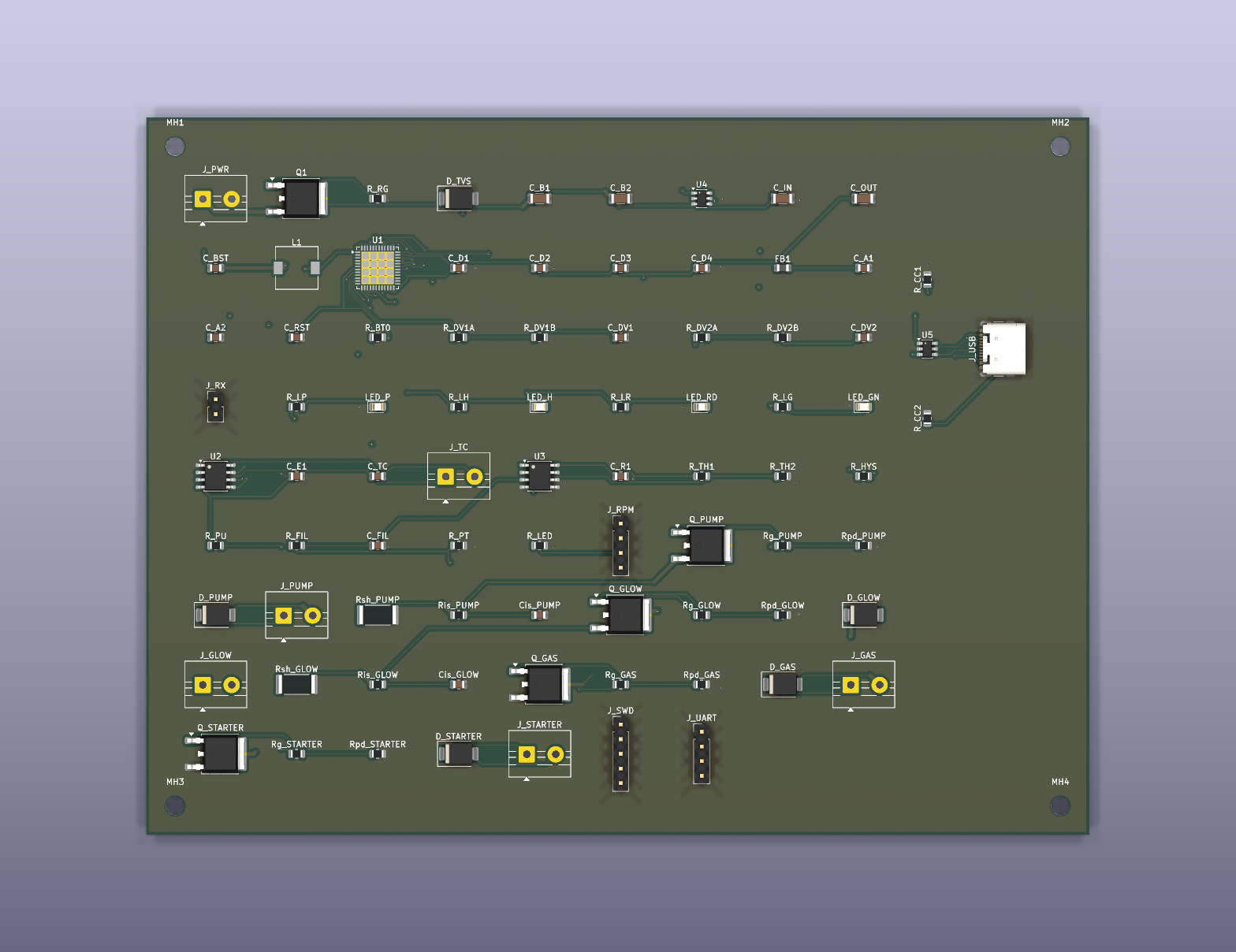
The analog side covers the whole engine interface: MAX31855 thermocouple input for exhaust gas temperature, an LM393 comparator front-end with hysteresis for RPM pickup, shunt-based current sensing on the actuators, a buck converter power stage, reverse-polarity ideal-diode protection, and USB-C with ESD protection.
The firmware
The core is portable, HAL-free C that compiles to the same object code on the STM32 and on the host, so the entire control system runs under CTest before it ever touches hardware. Five test suites, including a 20,000-iteration structural fuzz of the engine state machine and fault-injection coverage of every interlock.
The design rule that matters: the safety layer runs last on every 1 kHz tick and has final authority. It can only push outputs toward the safe state (fuel off, gas off). Hardware pull-downs keep actuators off through reset and brownout, and a ~250 ms watchdog backs it all up. Footprint: 24.2 KB flash, 8.4 KB RAM.
The wire protocol (COBS framing + CRC-16/CCITT) is generated from a single Python spec into C headers, a Python codec, protocol docs, and cross-language golden test vectors, making firmware/host drift structurally impossible.
The bench
A PySide6 desktop app (~1,900 lines) with live telemetry plots, a command console, parameter editor for the 22-entry tunable table, fault log, YAML-scripted test sequences that cannot bypass interlocks, and SQLite run logging with post-mortem analysis.
Before the hardware arrived, a software-in-the-loop simulator with a turbine plant model ran the full stack over TCP, including reproducing the original engine’s historical ignition-timeout failure mode: exactly the fault that killed the factory ECU’s usefulness in the first place.
Status
The board is built, and works (Kind of)!
I made several assumptions going into this, and a few were incorrect.
What Works
Power through the board, the firmware on the board, the connection to the computer with the software interface, driving the components (with the available current), EGT sensor readings, battery readings, shunt current readings all work. On the powered side, driving the glow plug works perfectly- and actually solves one of the core issues with the original ECS. Driving and throttling the fuel pump works, as well as the gas valve (which I didn’t use).
What Doesn’t Work
Driving the starter motor was.. a whole saga. I went in with a worst case assumption of
~20 A stall current and sized everything around that: a low-side IRLR7843 MOSFET, a 3 A
flyback diode, and fat 0.6 mm power traces, all running off the 2S pack at 6.0 to 8.4 V.
Then I spent most of a day convinced the board couldn’t drive it, because all I got was
horrible buzzing and usually no rotation at all.
Two things were actually going on, and neither one was the board.
First, my bench supply current limit was set too low. The motor needs about 5 A to break away from a standstill, and with the limit below that the supply dropped into constant current mode, the rail collapsed, and the voltage sag brown-out-reset the MCU. So the symptom presented as a firmware hang, and I chased phantom firmware bugs for hours before I thought to actually measure the breakaway current. Raising the limit to 8 A and the board spun the compressor on the first try, smoothly, with current dropping well below 5 A once it was actually turning (back-EMF). Worth noting: the winding measured 3.2 Ω, which predicts ~2.6 A. The resistance badly under-predicted reality. Trust the measurement, not the ohms.
Second, I was trying to start it at partial PWM duty. 22 % just made it buzz at the 100 Hz switching frequency. Breaking a stalled motor away needs peak torque, not gentle duty.
That second mistake is almost certainly what killed the motor. A motor that is buzzing but not turning is a locked rotor: it pulls full stall current, generates no back-EMF, and has no rotation moving heat out of the windings. That cooks a small motor much faster than simply running it flat out does. I later direct-drove it from the bench supply at 10 V, which also worked, right up until it didn’t.
So the board drives the starter fine. The FET, flyback and copper turned out to be roughly 4x oversized for the real load. What I actually have is a dead motor and a mechanical problem. I have some brushless motors lying around that I was hoping to use, but that won’t drop in: a BLDC needs a three-phase ESC doing electronic commutation, and my starter channel is a single low-side MOSFET that can only switch one load on and off. Replacing it means either a brushed motor, or adding an ESC and rethinking how the ECU commands it. I’m also still unsure how to properly mount it to the compressor wheel, and how to have it disengage once spool up is complete and the starter cuts out. That’s the current focus.
The RPM readings are also wrong. I assumed the factory sensor was a 4-wire reflective optical pair: an infrared emitter LED and a phototransistor watching a reflective target on the compressor wheel. The board is built entirely around that assumption. There’s a 220 Ω LED current limit, a 10 kΩ phototransistor load, an RC prefilter, and then an LM393 comparator with a fixed threshold at half the 3.3 V rail to square the analog signal into clean pulses, which feed a hardware timer that measures period rather than counting edges.
That is not what the sensor is. My best guesses now are a variable reluctance magnetic pickup or a Hall effect sensor, and the distinction matters a lot. A reluctance pickup generates its own AC voltage with amplitude proportional to speed, which means a fixed comparator threshold would never trip at low RPM, exactly when I most need the reading during spool up. Either way it needs different signal conditioning than what I built. I need to positively identify the sensor before I can fix it, and I can’t ignore it: RPM is the feedback that the entire start sequence and the overspeed protection depend on.
So the result so far is real progress, but still a ways to go. The starter motor and the RPM sensor are the two blockers, and both are more mechanical and analog front-end problems than firmware ones. Until I decide how to move forward on them, this project is on the backburner.