The goal
High bandwidth communications / data link with beam steering for maximum gain. This is also the stepping stone toward the counter-UAS radar work on the RF roadmap.
Two boards, one architecture
| 3×3 v1 | 4×4 v2 | |
|---|---|---|
| Elements | 9 | 16 |
| Phase shifters | MAPS-010145, 4-bit (22.5°) | HMC1133, 6-bit (5.625°) |
| Gain | ~9.5 dBi | ~12 dBi |
| Steering | ±60° | ±60° |
| Cost | ~$450 | ~$2,750 |
The 3×3 exists to de-risk the architecture at 83% lower cost before committing to the expensive board. Both target >1 kHz beam updates with IMU compensation, so the beam stays locked while the airframe moves.
Programmatic PCB
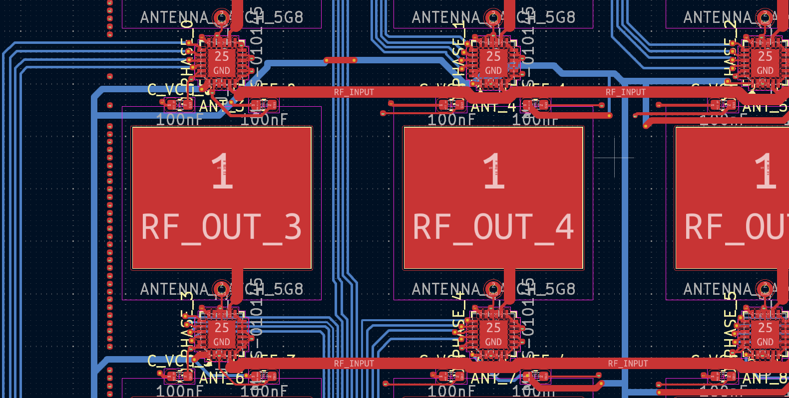
There is no hand-drawn schematic. Netlist, component placement, and routing are all generated from Python through KiCad’s scripting API: change the element count or spacing and regenerate the board. RF details are handled in code: 1.077 mm traces for 50 Ω on the Rogers layer, 0.3 mm neck-downs at component pads, curved corners, λ/2 patch spacing at 25.84 mm.
The stackup is the part I’m most pleased with: Rogers 4350B (0.508 mm, tan δ 0.0037) only on the top layer where the RF lives, FR4 below, joined with blind vias from two controlled-depth drill passes. About 30% cheaper than a full Rogers board with no meaningful RF penalty.
Control is an STM32H743: native SPI with 9 chip-selects on the 3×3, and twelve daisy-chained 74HC595 shift registers on the 4×4.
Status
Paused. The 3×3 is fab-ready (DRC clean, Gerbers generated) and has been sitting at “awaiting fab quote” since March 2026 while the turbine ECU and ground station ate the bench time. The 4×4 has RF layout done, routing pending. The companion simulator stays live so the beamforming work continues in software.